[PDF] Flowchart is a diagrammatic representation of an algorithm. Flowchart are very helpful in writing program and explaining program to others. Different symbols are used for different states in flowchart, For example: Input/Output and decision making has different symbols. The table below shows all the symbols that are used in designing flowchart.
|
Symbol |
Name |
Description |
| |
Flow line | Used to indicate the flow of logic by connecting symbols. |
| |
Terminal(Stop/Start) | Used to represent start and end of flowchart. |
| |
Input/Output | Used for input and output operation. |
| |
Processing | Used for arithmetic operations and data-manipulations. |
| |
Decision | Used to represent the operation in which there are two alternatives, true and false. |
| |
On-page Connector | Used to join different flow line |
| |
Off-page Connector | Used to connect flowchart portion on different page. |
| |
Predefined Process/Function | Used to represent a group of statements performing one processing task. |
Generally you can design a flowchart for programming with pencil and paper. People usually use flowchart drawing tool to design flowcharts for programming. There are many flowchart drawing tool through internet searching. A free flowchart drawing tool is enough for your use.
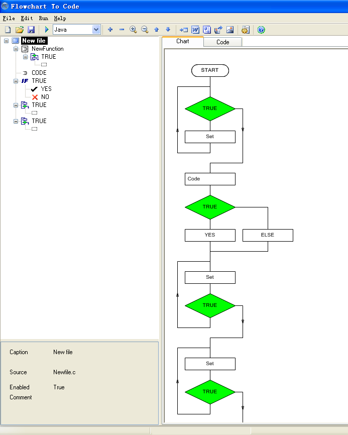
If you want to design a standard technical flowchart for writing program and explaining program to others, I will recommend you to use AthTek Flowchart to Code Converter. You can design a standard technical flowchart with this software. It doesn’t like any other flowchart drawing tool which cannot design a standard flowchart for programming. AthTek Flowchart to Code Converter provides a straight way to design a flowchart in programming. Software developer only needs to click the code tree in left area, and the standard flowchart will be created. What’s more, AthTek Flowchart to Code Converter supports to generate source code (in C/C++/C#/Java/JavaScript/Delphi) directly by the flowchart.